
Emission Control
Recovery of Volatile Organic Compounds from Gaseous Streams
A comparative technical and economic study of three VOC recovery technologies — refrigeration, absorption and adsorption — with industrial case studies showing savings running into hundreds of crores for Indian solvent-using industries.
Dr. D.M. Mohunta, Commercial, Chemical and Development Company
It is common to use volatile organic compounds, such as solvents and in some cases reactants, in chemical processing. It is also common to use volatile solvents in coating of webs or substrates such as for laminating, lacquering, etc. Solvents are also used in pharmaceutical processing. It is common to recover and recycle solvents in chemical plants, however an economically significant quantity is lost to the atmosphere.
The losses constitute a high air pollution load which is not permissible in most of the developed countries.
The paper indicates the sources of losses in chemical and other industries. The paper discusses three different modes such as refrigeration, absorption and adsorption. Technology, safety and economics are discussed with reference to actual cases.
Introduction
Volatile organic compounds are generally solvents and also many times reactants in the chemical industry. These are generated by many routes and find their way into the atmosphere. The loss of these to the atmosphere constitutes an economic loss and also it pollutes the atmosphere.
In recent years the main driving force worldwide for the recovery and recycle or alternate disposal has been the stringent pollution laws. In India there are hardly any emission standards on VOC except for few like benzene and hydrocarbons and therefore there is very little concern. The only incentive being the recovery of investment as fast as possible. The other deterrent has been the capital cost in spite of good ROI.
VOC emissions occur from many sources such as:
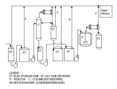
- Storage vents
- Distillation vents
- Reactor vents
- Mixers
- Pan coolers
- Spray dryers/granulators
- Coating, printing and laminating machines always give low concentration of vapours.
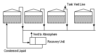
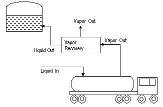
- In the storage systems emission occur during filling of tank, transferring of liquid from/to sea going tankers and road/rail tankers.

Safety
It is considered safe to operate a system either below the lower explosive limit (LEL) or above the upper explosive limit (UEL). Generally the vapours from the high concentration system mentioned above are UEL. In the case of low concentration systems many times additional dilution has to be resorted to keep well below the LEL.
Only in the case of marine unloading it is specified that it has to be above the upper explosive limit.
Thus we may divide the VOC recovery systems into two types based on whether it is high concentration or low concentration.
The recovery systems could be categorized as below:
- Refrigeration based systems
- Absorption based systems
- Adsorption based systems
Refrigeration System
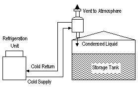
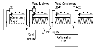
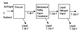
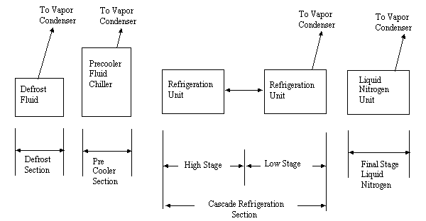
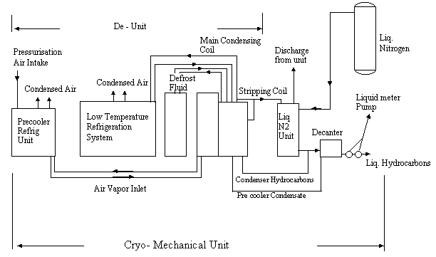
The refrigeration based systems depend upon the cooling of the effluent gas to a temperature sufficiently low so that the VOC is condensed out to the desired extent. The temperature for mechanical refrigerated system can be as low as -70°C; beyond this temperature, a combination of mechanical and cryoscopic cooling can be used. Thus with liquid nitrogen temperatures as low as -180°C can be achieved.
Absorption System
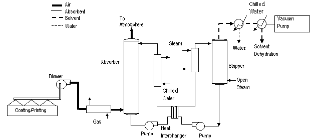
In this system the VOCs are absorbed in a suitable high boiling solvent at low temperature in an absorption tower and then desorbed by heating the solvent directly or indirectly. The desorbed gases which have high concentration of VOC are then condensed; it may become necessary sometimes to use refrigerated condensing system to meet emission standards from the condenser vents.
Adsorption System
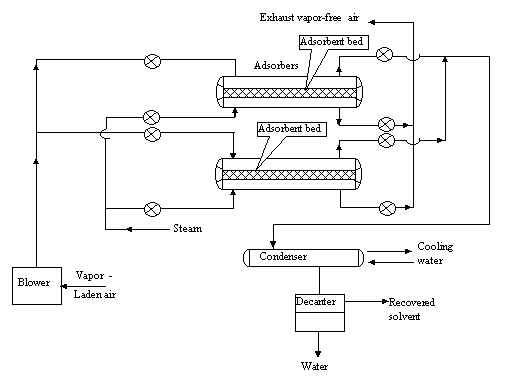
The VOC is adsorbed in a suitable adsorbent, usually activated carbon. When the bed is saturated the gases are switched to another bed and the VOC matter is then desorbed by heating directly or indirectly the bed of activated carbon.
The concentrated gases that come out are condensed. Refrigeration systems can be added in series to meet emission standards if required. In contrast to the above two systems this is a batch process.
Given below are the essential features of each of the systems. (Table 1)
Features of Refrigeration Systems
Refrigeration systems are mainly used for concentrated gases such as emission from storage tanks and filling systems process vents.
- It does away with one step of separation of the VOC from the inerts.
- The refrigeration load goes up considerably as concentration of non-condensable increases.
- To some extent this is mitigated by heat interchange between inlet and outlet gases.
- As the gas becomes leaner the temperature of condensation reduces.
- The system is inherently safe as it operates at very low temperatures.
- The system pressure drop is very low.
- It has high turn down ratio from 0-100%.
- Ease of performance monitoring — EPA requires only the outlet temperature to be monitored.
- Does not require concentration measurement.
- Low power cost as the units consume power on demand.
- Low maintenance — only preventive maintenance is required.
- No cost of carbon replacement or solvent replacement.
- System can take care of water content in influent stream.
- Systems are pre-engineered and come in modules.
Features of Absorption Systems
- Choice of correct absorbent is required so that the absorbent losses are low and equilibrium concentration is high.
- System operates continuously at all loads.
- Can use low concentrations of VOC typically 0.5%.
- High concentration of VOC would require high circulating volumes due to equilibrium requirements.
- System requires some on site engineering and erection etc.
- System is fully automatic.
- Requires outlet gas concentration measurement.
- System can be engineered for small footprint.
- Permits partial separation of components.
- Requires vacuum to limit temperature of desorption.
Features of Adsorption Systems
- Used for low concentration of VOC typically 0.5%.
- Requires large number of beds.
- It is batch process requiring switching of streams from bed to bed.
- Periodic replacement of activated carbon.
- Large volumes of organics are kept in process presenting a safety hazard.
- Periodic regeneration of beds with steam or inert air.
- Large installation cost.
- Requires condensation of outlet gases.
- Requires measurement of concentration of outlet gas.
- Limit to size of activated carbon beds due to heat transfer considerations.
- Because of large size of installation possibility of air ingress and explosions as the unit has to operate above ignition temperature.
- Activated carbon quality can vary between manufacturers and the size of equipment, etc. will also vary.
Problem of Moisture in Effluent
The moisture in effluent gases in case of refrigerated systems tend to form ice on the heat exchange surfaces and in case of many hydrocarbons there is formation of hydrates. This situation would also arise when condensing after use of absorption or adsorption systems if emission norms have to be met.
The condenser for such systems are finned heat exchangers of special design so that the time to become frosted can be specified. If the usage is intermittent the interval can be used for defrosting. If it is process continuous then dual condensers have to be used.
As the temperature is very low, as low as -70°C, special chemicals like D-limonene which have very low freezing point have to be used for defrosting otherwise the defrosting fluid itself would freeze.
Purity of Recovered Solvent
The condensed solvent will usually contain water; the sources are from the moisture in gas stream or addition of steam during stripping. It becomes necessary to remove the water so that the recovered solvent can be recycled. Various methods have been employed depending upon the type and mixture of solvents:
- Azeotropic distillation
- Molecular sieve adsorption
- Membrane separation
- Chemical dehydration
It will be useful to compare the costs of recovery in order to evaluate the adoption of a procedure. Given below is a comparison of operating costs of recovery by different methods.
Example 1 — Acetone Recovery
| Parameter | Value |
|---|---|
| Gas flow rate | 487 m³/hr |
| Acetone content | 123 gms/m³ |
| Temperature | 28°C |
| Solvent loss per year | Rs 185 lacs |
| Recovery target | 90% |
The highest operating cost is by using carbon bed adsorption Rs 7.47/kg, refrigeration systems costs are lower Rs 5.70/kg, and the lowest cost is by absorption, Rs 2.27/kg. It has not been possible to get comparable capital costs as the source of equipments are from different countries.
Example 2 — Multi-Solvent Recovery
| Parameter | Value |
|---|---|
| Gas flow rate | 9,500 m³/hr |
| VOC content | 97 gms/m³ |
| Composition | Ethyl Acetate, Toluene, MEK, Cellosolve |
| Solvent loss per year | Rs 271 lacs |
| Recovery target | 90% |
The refrigeration operating cost is extremely high as final condensing temperature of -60°C is required. The connected load would be approximately 400 HP.
The operating cost of absorption system is Rs 7.30/kg and for adsorption system Rs 10.6/kg.
It should be noted that in the above cases the emphasis is on recovery at the lowest cost. The vent concentration may be above those specified under emission standards; to comply with standards it may require refrigeration down to -30 to -40°C, however the additional cost will be very much lower than for direct refrigeration, as the quantity to be processed would be very small.
Example 3 — Hydrocarbon Recovery from Tanker Loading
Hydrocarbon recovery from a tanker loading installation using refrigeration technology. The loading installation loads petroleum products mainly gasoline into road or rail tankers.
| Parameter | Value |
|---|---|
| Road tankers loaded per day | 480 m³/day |
| Rail tankers loaded per day | 1,530 m³/day |
| Max throughput | 760 m³/hr |
| % hydrocarbon in gas stream | 50% |
| Emission standard | 35 mg/litre of hydrocarbon loaded |
| Recovery | 99% |
| Operating days per year | 310 |
| Gasoline recovery | 1,460 kl/year |
| Annual power cost | 164,500 kWh, Rs 8.75 lacs |
| Recovery value at Rs 30/litre | Rs 468 lacs |
| Connected load | 132 kW |
| Temperature | -10°C |
| Cost of recovery plant | Rs 400 lacs |
| Size | 9′w × 60′l × 11′h |
| Weight | 23 metric tons |
The above are actual examples and it can be seen that the scope in savings is enormous. There are dozens of oil filling installations in India, and there are thousands of units using solvents. The total savings to the nation and individual companies can run into hundreds of crores.
Conclusion
Three main types of VOC recovery technologies are available. The technologies are cost effective per se. Among the technologies there are cost differentials depending upon the concentrations used and other factors.
The use of VOC recovery systems can save crores of rupees for individual industries and to the nation. It will also make these units more competitive.
Acknowledgement
Information has been provided by M/s Edwards Engineering, USA for refrigeration systems, FEDES — France, DEC Impianti — Italy for adsorption systems; the absorption system design and data is in-house.
The company is headed by Dr. Mohunta who has 45 years of experience in the Chemical industry.