
Process Design
Continuous Production of Meta-Bromobenzaldehyde (MBB)
A conceptual continuous process for meta-bromobenzaldehyde — replacing batch reactors with CSTRs in series for 3x productivity, 88-90% yield (vs 82-84% batch), and 65% lower working capital.
Technical Report – September 2020
Author: Dev Mohunta · commercial chemical and development company · dmm@ccdindia.com
INTRODUCTION
In the production of cypermethrin, one of the key reactants is meta‑phenoxybenzaldehyde (MPB). Thousands of tonnes are produced annually in India and worldwide, to match the production of cypermethrin. MPB is usually produced by a five‑step organic reaction and the first step is the production of meta‑bromobenzaldehyde (MBB).
The synthetic organic chemical industry is a prime example of the extensive use of batch type chemical reactors. However, moving from batch to a continuous reaction regime, allows for the possibility of lower capital costs, smaller size of plant, lower cost of production, improved yields, lesser by‑products, and a cleaner and safer process.
Chemistry
To prepare MBB, Benzaldehyde (BZH) is reacted in a solvent medium with mixture of bromine and chlorine in the presence of anhydrous aluminum chloride (AlCl₃).
The overall reaction that takes place is:
C₆H₅CHO + ½Br₂ + ½Cl₂ →(AlCl₃) BrC₆H₅CHO + HCl↑
Step‑wise reactions are as below:
- Br₂ + Cl₂ → 2 BrCl
- BrCl + AlCl₃ → AlCl₄⁻ + Br⁺
- C₆H₅CHO + Br⁺ → BrC₆H₅CHO + AlCl₄⁻
- BrC₆H₅CHO + AlCl₄⁻ → BrC₆H₅CHO + AlCl₃ + HCl
The heat of reaction is 25.153 kcal/mole.
In practice, the batch reaction is carried out in a chlorinated solvent such as ethylene dichloride (EDC). AlCl₃ is dissolved in dry EDC and required quantity of BZH; the mixture is cooled and bromine is added. The reaction mixture is maintained at a temperature of about 10°C. Chlorine is sparged into the reactor, while maintaining the temperature. During the reaction, HCl gas is evolved, which is scrubbed with water, and converted to 32% hydrochloric acid. The reaction is not carried out to maximum conversion of benzaldehyde, but terminated at an earlier conversion to avoid decrease in yield and increased impurities.
The reaction mixture is further processed by drowning in water and the organic phase is separated and washed repeatedly. The organic phase, containing the solvent EDC and excess of reactants, is subjected to multiple distillations to recover and recycle benzaldehyde and purify MBB. The main impurities are mono‑chlorobenzaldehyde (MCB) and higher boiling compounds, referred to as HR, which are mainly di‑halogen compounds.
Generally excess amounts of reactants are taken for the reaction – bromine 10%, BZH 20% and AlCl₃ 30% molal excess respectively. It is not possible to say with any degree of certainty how these quantities have been arrived at, as no literature is available except that described in texts and reference books on organic synthesis chemistry.
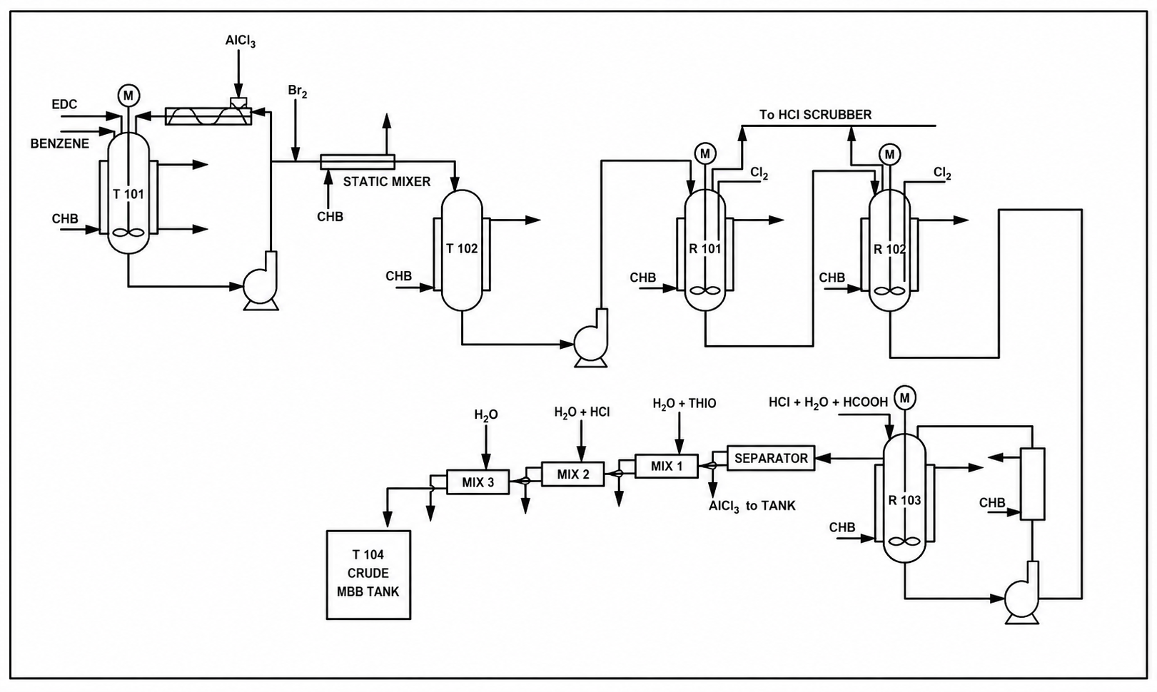
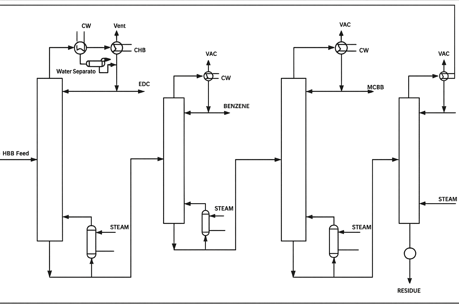
Presented here is a conceptual process for the manufacture of MBB. The reactor design is based on experimental laboratory data. The process flowsheet (Figures 1 and 2) shows the process, including workup and purification. For the comparison of batch vs continuous process, standard glass‑lined reactor of 6.3 kl capacity is adopted.
Making of reaction mixture
The reaction mixture is made in jacketed mixing tank, T101. Chilled water is used for cooling. Distilled mixture of EDC and BZH is added to it, and more EDC and BZH added to make up the required ratio. The mixture is circulated through a cooler and a screw conveyor mixer, where required quantity of aluminium chloride (AlCl₃) is added.
Addition of bromine
Bromine addition is done in a continuous manner. Chilled brine is circulated in the jacket of receiving vessel, T102. The mixing of EDC/BZH and bromine is done by metering them and feeding them to chilled brine cooled static mixer. The temperature is maintained at 10°C.
Chlorination
This a combination of two CSTR reactors in series. These are glass‑lined reactors and the gas outlet is connected to HCl scrubber. The reaction mixture, as prepared as above, is fed at steady rate into the reactor, R101, and chlorine at a metered rate is sparged into it. The mixture then flows to reactor, R102, where more chlorine is sparged. Strict temperature control is to be maintained during the addition of chlorine.
Drowning
The overflow from reactor, R102, is drowned in R103 in a very dilute HCl and formic acid solution. The solution is separately prepared and added continuously. The overflow from R103 is fed to the suction of a forced circulation external heat exchanger to provide mixing and cooling. The contents form two layers – a water layer and EDC organic layer. The mix goes to a separator. EDC is the heavier layer and is at the bottom, while the aqueous layer is the upper layer, and has to be disposed. There is some evolution of gas during this operation and a scrubber is required.
Washing
This is done in three mixer‑settlers. In the first mixer‑settler, MSX 1, a wash is given with dilute thiosulphate solution. The wash‑water goes for effluent treatment. The organic layer goes to second mixer‑settler, MXS 2, where a wash is given with dilute HCl. The organic layer then goes to third mixer‑settler, MSX 3, where a water wash is given and the organic layer, which is crude MBB, goes to storage tank.
Recovery and purification
The crude MBB is processed in four distillation columns. The first distillation column is of glass and others are made from SS. All the four columns operate under varying degrees of vacuum.
In the first column, distillation is done under 550‑mm Hg pressure. This is a MSGL column with ceramic packing, and graphite heat condenser. The overhead product purity is assumed to be 99.9%. The bottoms would contain 4‑5% EDC, which would be recovered along with BZH.
The bottoms from the EDC column are fed to the benzaldehyde recovery column. The top product is benzaldehyde with some EDC, and the bottoms containing MCB + MBB and residue is fed to the MCB recovery column. The MCB recovery column is of SS with structured packing. It recovers MCB with a purity of 99% which is a saleable product.
The bottoms from third column are fed to the MBB distillation column, to obtain a high purity product, and the bottoms are high boiling multi‑halogen compounds.
Adoption of a continuous distillation system, instead of batch distillation, avoids the repeated recycle of fore‑cuts, mid‑cuts, etc. The columns are also smaller in size.
Figure 2 — MBB Distillation (flowchart)
Continuous vs Batch
The yield in a continuous process is approximately 88‑90% compared to 82‑84% by batch process. A system described above with two 6.3 kl MSGL reactors can produce approximately 168 tonnes per month (tpm). The hourly rate would be about 275 kg/hr.
Productivity
Batch process
From the information obtained from industrial sources, a reaction time of 10‑14 hours for a conversion of 82% wt. is indicated and the average batch time from charging to cleaning is approximately 30 hours. The production capacity is 30 tpm for a 6.3‑kl reactor. The overall productivity is a dismal 7.7‑kg/m³/hr (at 85% equipment availability). To produce 168 tpm, five reactors of 6.3‑kl will be required with multiple facilities for charging, cooling, pumping, gas absorption, etc.
Continuous process
The continuous process requires just two reactors of 6.3‑kl for the same capacity. The productivity is 21.87‑kg/m³/hr, i.e. about three times of the batch process.
Work in Progress (WIP)
WIP represents a capital block for which there is financial cost. Reducing this reduces overhead costs. For the reactor system alone WIP is approximately 30 m³ for a batch process, and 10 m³ for a continuous process. As a consequence, the working capital is reduced by about 65% in the latter. There is similar reduction in the work up and distillation sections.
Operations
The continuous plant has to be well instrumented for control and monitoring, thus reducing high labour costs typically associated with batch processes. There is also a significant reduction in capacity of utilities, as only few hundred kilograms of products are being processed at any time. For example, all pumps are of smaller capacity.
CONCLUSION
Here is an example of a slow reaction that can be considerably improved by making it continuous. The equipment productivity increases three times. There is also a significant improvement in yield from 82‑84% to 88‑90%. The plant footprint is reduced, and there is significant reduction in operating costs, capital costs, and overheads.